MECHAN
Mechan - SSS, SSC, SSR coded safety switch
The SS range of electronically coded safety switches offer greater tamper resistance than standard magnetically operated switches. The units are fully encapsulated into resin filled ABS housings and have a status LED for visual indication of operation.
When the actuator is brought to the sensing part of the switch (within 8-10mm target to target) a dynamic signal is generated in the actuator and transmitted to the sensor. This signal will, along with a secondary switching system, allow the safety control relays to energise thus closing the safety contacts and opening the signal contacts.
Technical specification
| SSS | SSC | SSR |
Power supply | 24Vdc | ||
Power consumption | 2VA | ||
Safety contact rating | 2A @ 230Vac or 30Vdc | 500mA @ 110Vac or 24Vdc | 2A @ 230Vac or 24Vdc |
Auxiliary contact rating | 2A @ 230Vac or 30Vdc | 500mA @ 110Vac or 24Vdc | 2A @ 230Vac or 24Vdc |
External fuse (not supplied) | 3A fast acting | ||
Operating temperature | -10°C to +55°C | ||
Storage temperature | -20°C to +60°C | ||
Housing | Blue ABS case, resin filled | ||
Protection | IP67 | ||
Vibration/shock | 50-100Hz/10g | ||
Switching distance | 6-9mm on, 10-12mm off | ||
Optimum gap | 2mm | ||
Max. cable length | 100 metres | ||
Indication | Green LED | Dual colour LED (red/green) | Dual colour LED (red/green) |
Mounting | M4 security screws (supplied) | ||
Dimensions
|
|
SSR |


Mounting
The SSS safety switches can approach each other from any angle. |


Ordering information
Part number | Output contacts | Cable length |
SSS-11-03M | 1 normally open safety, 1 normally closed auxiliary | 3m |
SSS-20-03M | 2 normally open safety | 3m |
SSS-11-QD-05M | 1 normally open safety, 1 normally closed auxiliary | 5m quick disconnect |
SSS-20-QD-05M | 2 normally open safety | 5m quick disconnect |
SSS-QD-CABLE-05M |
| 5m, 6pin cable only |
SS-C-03M | 1 normally open safety, 1 normally closed auxiliary | 3m |
SS-C-05M | 1 normally open safety, 1 normally closed auxiliary | 5m |
SS-C-10M | 1 normally open safety, 1 normally closed auxiliary | 10m |
SS-R-03M | 2 normally open safety, 1 normally closed auxiliary | 3m |
SS-R-05M | 2 normally open safety, 1 normally closed auxiliary | 5m |
SS-R-10M | 2 normally open safety, 1 normally closed auxiliary | 10m |
Please Note: Other cable lengths available on request.
- Dual colour LED status indication
- IP67 sealing
- 8-10mm switching distance
- Choice of output contacts


Selected variant
Specifications
| Safety contact NO | 1 |
|---|---|
| Signal contact NC | 1 |
| Contact Current Max | 500 mA |
| Activation Distance From | 7 mm |
| Activation Distances | 11 mm |
| Material Case | ABS plastic |
| IP Class | IP67 |
| Temperature range from | -25 °C |
| Temperature range to | 55 °C |
| B10d | 2,0 milj. |


Product description
The SS range of electronically coded safety switches offer greater tamper resistance than standard magnetically operated switches. The units are fully encapsulated into resin filled ABS housings and have a status LED for visual indication of operation.
When the actuator is brought to the sensing part of the switch (within 8-10mm target to target) a dynamic signal is generated in the actuator and transmitted to the sensor. This signal will, along with a secondary switching system, allow the safety control relays to energise thus closing the safety contacts and opening the signal contacts.
Technical specification
| SSS | SSC | SSR |
Power supply | 24Vdc | ||
Power consumption | 2VA | ||
Safety contact rating | 2A @ 230Vac or 30Vdc | 500mA @ 110Vac or 24Vdc | 2A @ 230Vac or 24Vdc |
Auxiliary contact rating | 2A @ 230Vac or 30Vdc | 500mA @ 110Vac or 24Vdc | 2A @ 230Vac or 24Vdc |
External fuse (not supplied) | 3A fast acting | ||
Operating temperature | -10°C to +55°C | ||
Storage temperature | -20°C to +60°C | ||
Housing | Blue ABS case, resin filled | ||
Protection | IP67 | ||
Vibration/shock | 50-100Hz/10g | ||
Switching distance | 6-9mm on, 10-12mm off | ||
Optimum gap | 2mm | ||
Max. cable length | 100 metres | ||
Indication | Green LED | Dual colour LED (red/green) | Dual colour LED (red/green) |
Mounting | M4 security screws (supplied) | ||
Dimensions
|
|
SSR |
Mounting
The SSS safety switches can approach each other from any angle. |
Ordering information
Part number | Output contacts | Cable length |
SSS-11-03M | 1 normally open safety, 1 normally closed auxiliary | 3m |
SSS-20-03M | 2 normally open safety | 3m |
SSS-11-QD-05M | 1 normally open safety, 1 normally closed auxiliary | 5m quick disconnect |
SSS-20-QD-05M | 2 normally open safety | 5m quick disconnect |
SSS-QD-CABLE-05M |
| 5m, 6pin cable only |
SS-C-03M | 1 normally open safety, 1 normally closed auxiliary | 3m |
SS-C-05M | 1 normally open safety, 1 normally closed auxiliary | 5m |
SS-C-10M | 1 normally open safety, 1 normally closed auxiliary | 10m |
SS-R-03M | 2 normally open safety, 1 normally closed auxiliary | 3m |
SS-R-05M | 2 normally open safety, 1 normally closed auxiliary | 5m |
SS-R-10M | 2 normally open safety, 1 normally closed auxiliary | 10m |
Please Note: Other cable lengths available on request.
Related

Fully assembled safety edges
With the help of our technical department, we can offer efficient and comprehensive delivery of safety edges, ready for plug-and-play installation.

Safety systems and intelligent detection
Inxpect safety radars detect access or presence of operators in dangerous areas and also have the ability to dynamically set the detection and warning zones.

SH4 safety curtains
Safety curtains and beams provide effective and reliable personal protection and monitoring in a wide range of industrial environments.
Versatile properties in small size 80x80x95 mm
Hokuyo has small safety laserskanner that is very small in size. This versatile laserskanner fits in most systems. Read more!
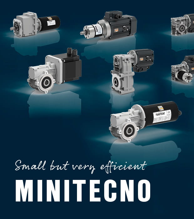
Small but very efficient gear motors
Transtecno has developed the MiniTecno product range to better meet the needs of customers using small gear motors in a wide range of industries, up to 90 Nm.

Products for hygienic applications
WIKA's hygienic products take into account the high hygiene, cleaning, and durability requirements of the food and pharmaceutical industries. Read more!
