PULS
24 V dc UPS for external battery 3.9-130 Ah
The UB20.241 uninterruptible power supply controller (DC-UPS) is used in addition with a 24V power supply and batteries to bridge power failures or voltage fluctuations. This configuration can prevent expensive downtimes, long restart cycles and loss of data.
A unique feature of the UB20 series is the constant voltage in battery mode, which will not change as the batteries discharge. The buffer voltage in battery mode can be set to four different output values. Another feature is the utilization of two independent battery chargers for the two 12V-batteries in series. This feature makes matching batteries unnecessary and allows for precise battery charging, testing and optimized usage of the battery capacity to achieve the longest battery service life.
The UB20.241 includes many battery diagnostic functions that ensure a reliable operation of the entire system. Furthermore, a temperature controlled charging
extends the life of the batteries. It also includes a selectable buffer time limiter as well as ready, buffering and replace battery contacts. For safety and
maintenance, an inhibit input signal is included which prevents a battery backup.
Technical Data
Input/Output | ||
Input voltage from the unit | 24 V DC (23.3-30 V DC continuous operation) | |
Input voltage from the battery | 2x12 V DC two batteries in series | |
Output voltage during normal operation | 0.15 V DC lower than the input voltage from the power supply | |
Output voltage in battery mode | Selectable via switches in the front. 22.5, 24, 25 or 26 VDC. | |
Output current during normal operation via the unit (max.) | 25 A. If feeding unit is greater than 28 A, a 25 A fuse between the unit and the control unit is installed. | |
Output current in battery mode (max.) | 20 A (30 A for 4s, then the output is set in the "hick-up" mode) | |
Input current internal consumption type | 70 mA | |
Input current when charging from supply 24 V DC | 1.7 A battery switch in position <10 Ah 3.4 A battery switch in position >10 Ah | |
*The total input power when the battery is charging | 1.77 A or 3.47 A | |
| ||
Permitted battery sizes | 3.9-130 Ah | |
Charging the battery type | 1.5 A battery switch in position <10 Ah 3 A battery switch in position >10 Ah | |
Charging type | Ex. 8 hours 12 Ah completely discharged battery | |
Voltage level of the connection of the battery | Identical to the selected output voltage in battery | |
Selectable buffer times | 10 s, 30 s, 1 m, 3 m, 10 m alt. endlessly until deep discharge protection becomes | |
Buffer with 2x7 Ah battery ** | Min. 13.3 min at 10 A. Typ. 16.53 min at 10 A | |
Min. 4 min at 20 A. Typ. 5.12 min at 20 A | ||
Buffer with 2x12 Ah battery ** | Min. 35.3 min at 10 A. Typ. 44.3 min at 10 A | |
Min. 11.53 min at 20 A. Typ. 14.51 min at 20 A | ||
External temp. | PT-1000. See the "Wiring" tab. | |
Power loss type | 3.7 W Supply via power supply, 20 A load current and the battery is fully charged. | |
| ||
| 22.7 W. Supply via battery, 20 A load current | |
Operating temperature controller | -40 to +70 °C (some power reduction over +60 °C). | |
Connection power | Screw connection. 2.5-4 mm² multifilament, 2.5-6 mm² monofilament | |
Connection signal contacts | Connector terminals. 0.2-1.5 mm² | |
Weight | 700 g | |
Dimensions WxHxD (mm) | 46x124x127. (Supplement for signal contacts in height and DIN rail length) | |
Signal contacts | Ready. Controller ready for backup. | |
| Buffering. Control of backup / battery mode. | |
| Repl. Bat. Battery replacement | |
Input inhibit | External shutdown by 24 V DC. Min. pulse time 250ms. Max 35 V DC. | |
MTBF enl. SN 29500, IEC 61709, 20 A and 40 °C | 649 000 hours (Operation with power supply) | |
Approvals | CE, UL508 Listed, UL 60950-1, CB-Scheme | |
EMC | EN 61000-6-1, EN 61000-6-2, EN 61000-6-3, EN 61000-6-4. | |
Compliant standards | EN/ IEC 60204-1, EN/IEC 61131-2, EN50178, IEC 62103 | |
* The total input power must be deducted from the unit's rated current, the result is the maximum available load current. Ex. 20 A units is the maximum load current 16.53 A with battery> 10 Ah. 3.47 A is used for internal consumption and charging of the batteries.
** The minimum value of 20% include the aging of the battery and a cable length of 1.5 meters with the area 4 mm² between battery and controller.
Backup times
Discharge curve |
|

Dimensions & wiring
Dimensions | |
|
|


Wiring | |
| |
| |
Connecting the center tap of the treatment of the batteries separately | |
| |
For optimized charging and longevity required that each battery is controlled separately. We recommend connecting the midpoint of the batteries with a center drain connection on the controller to achieve maximum performance. Install a 4 A fuse between the battery and the controller. | |
| |
Connection of a complete DC UPS systems | |
| |
| |
Ventilation | |
Install the battery so that it does not get heated by adjacent equipment and ensure that there is proper ventilation according EN50272-2. | |


Part Numbers
Order number | Description |
UB20.241 | DC-UPS module for battery. 24 V DC/20 A |
UZO24.071 | Battery holder for DIN rail. For battery 7 Ah |
UZO24.121 | Battery holder for DIN rail. For 2x12 Ah batteries |
- Load current 20 A
- Control of each individual battery
- Selectable output voltage in battery mode
- Temperature compensated charging
- Relay outputs for status


Selected variant
Specifications
| Input Voltage From The Unit | 24 V DC |
|---|---|
| Input Voltage From battery | 24 V DC |
| Input voltage for battery connection | 22.8 V DC |
| Input Current During Charging Of Aggregates | 3.4 A |
| Type Power Supply | DC-UPS |
| Output current at 24 V dc | 20 A |
| Power Reduction Of 60 To 70 ° C | 12 W/°C |
| Output Voltage at Battery | 22.5 |
| Output Voltage Normal Operation | 24 V DC |
| Output current for battery operation max | 20 A (30 A @ 4 s) |
| Output Current During Normal Operation Via The Unit Max | 25 A |
| Ripple. max | 120 mV pp |
| Temperature Range Without Derating From | -40 °C |
| Temperature Range Without Derating To | 60 °C |
| Efficiency | 99 % |
|---|---|
| Life span | 122 000 h @ 20 A, 40 °C |
| MTBF (IEC 61709) | 649 000 h @ 20 A, 40 °C |
| Width | 49 mm |
| Height | 124 mm |
| Depth | 117 mm |
| Weight | 0.7 kg |
| Approvals | ABS, CB, CE, CSA, CSA US, EX, GL, IECEx, UL |
| Material Protection | Aluminium |
| IP Class | IP20 |
| Charging The Battery Type | 3 A |
| Voltage Level Of The Connection Of The Battery | 24 V DC |
| Permitted Battery Sizes | 3,9-150 Ah |


Product description
The UB20.241 uninterruptible power supply controller (DC-UPS) is used in addition with a 24V power supply and batteries to bridge power failures or voltage fluctuations. This configuration can prevent expensive downtimes, long restart cycles and loss of data.
A unique feature of the UB20 series is the constant voltage in battery mode, which will not change as the batteries discharge. The buffer voltage in battery mode can be set to four different output values. Another feature is the utilization of two independent battery chargers for the two 12V-batteries in series. This feature makes matching batteries unnecessary and allows for precise battery charging, testing and optimized usage of the battery capacity to achieve the longest battery service life.
The UB20.241 includes many battery diagnostic functions that ensure a reliable operation of the entire system. Furthermore, a temperature controlled charging
extends the life of the batteries. It also includes a selectable buffer time limiter as well as ready, buffering and replace battery contacts. For safety and
maintenance, an inhibit input signal is included which prevents a battery backup.
Technical Data
Input/Output | ||
Input voltage from the unit | 24 V DC (23.3-30 V DC continuous operation) | |
Input voltage from the battery | 2x12 V DC two batteries in series | |
Output voltage during normal operation | 0.15 V DC lower than the input voltage from the power supply | |
Output voltage in battery mode | Selectable via switches in the front. 22.5, 24, 25 or 26 VDC. | |
Output current during normal operation via the unit (max.) | 25 A. If feeding unit is greater than 28 A, a 25 A fuse between the unit and the control unit is installed. | |
Output current in battery mode (max.) | 20 A (30 A for 4s, then the output is set in the "hick-up" mode) | |
Input current internal consumption type | 70 mA | |
Input current when charging from supply 24 V DC | 1.7 A battery switch in position <10 Ah 3.4 A battery switch in position >10 Ah | |
*The total input power when the battery is charging | 1.77 A or 3.47 A | |
| ||
Permitted battery sizes | 3.9-130 Ah | |
Charging the battery type | 1.5 A battery switch in position <10 Ah 3 A battery switch in position >10 Ah | |
Charging type | Ex. 8 hours 12 Ah completely discharged battery | |
Voltage level of the connection of the battery | Identical to the selected output voltage in battery | |
Selectable buffer times | 10 s, 30 s, 1 m, 3 m, 10 m alt. endlessly until deep discharge protection becomes | |
Buffer with 2x7 Ah battery ** | Min. 13.3 min at 10 A. Typ. 16.53 min at 10 A | |
Min. 4 min at 20 A. Typ. 5.12 min at 20 A | ||
Buffer with 2x12 Ah battery ** | Min. 35.3 min at 10 A. Typ. 44.3 min at 10 A | |
Min. 11.53 min at 20 A. Typ. 14.51 min at 20 A | ||
External temp. | PT-1000. See the "Wiring" tab. | |
Power loss type | 3.7 W Supply via power supply, 20 A load current and the battery is fully charged. | |
| ||
| 22.7 W. Supply via battery, 20 A load current | |
Operating temperature controller | -40 to +70 °C (some power reduction over +60 °C). | |
Connection power | Screw connection. 2.5-4 mm² multifilament, 2.5-6 mm² monofilament | |
Connection signal contacts | Connector terminals. 0.2-1.5 mm² | |
Weight | 700 g | |
Dimensions WxHxD (mm) | 46x124x127. (Supplement for signal contacts in height and DIN rail length) | |
Signal contacts | Ready. Controller ready for backup. | |
| Buffering. Control of backup / battery mode. | |
| Repl. Bat. Battery replacement | |
Input inhibit | External shutdown by 24 V DC. Min. pulse time 250ms. Max 35 V DC. | |
MTBF enl. SN 29500, IEC 61709, 20 A and 40 °C | 649 000 hours (Operation with power supply) | |
Approvals | CE, UL508 Listed, UL 60950-1, CB-Scheme | |
EMC | EN 61000-6-1, EN 61000-6-2, EN 61000-6-3, EN 61000-6-4. | |
Compliant standards | EN/ IEC 60204-1, EN/IEC 61131-2, EN50178, IEC 62103 | |
* The total input power must be deducted from the unit's rated current, the result is the maximum available load current. Ex. 20 A units is the maximum load current 16.53 A with battery> 10 Ah. 3.47 A is used for internal consumption and charging of the batteries.
** The minimum value of 20% include the aging of the battery and a cable length of 1.5 meters with the area 4 mm² between battery and controller.
Backup times
Discharge curve |
|
Dimensions & wiring
Dimensions | |
|
|
Wiring | |
| |
| |
Connecting the center tap of the treatment of the batteries separately | |
| |
For optimized charging and longevity required that each battery is controlled separately. We recommend connecting the midpoint of the batteries with a center drain connection on the controller to achieve maximum performance. Install a 4 A fuse between the battery and the controller. | |
| |
Connection of a complete DC UPS systems | |
| |
| |
Ventilation | |
Install the battery so that it does not get heated by adjacent equipment and ensure that there is proper ventilation according EN50272-2. | |
Part Numbers
Order number | Description |
UB20.241 | DC-UPS module for battery. 24 V DC/20 A |
UZO24.071 | Battery holder for DIN rail. For battery 7 Ah |
UZO24.121 | Battery holder for DIN rail. For 2x12 Ah batteries |
Add product as a new cart row
You already added this product. Choose whether to increase quantity on the existing row or add the product as a new row.
Related
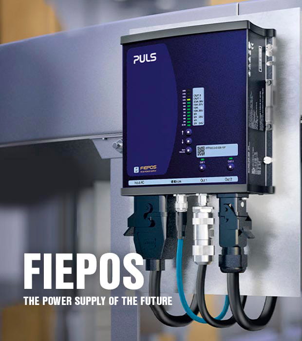
Fiepos — The power supply of the future
The need for flexible, modular systems shapes machine and system engineering. Decentralization of the system components has proven to be an important factor for success.
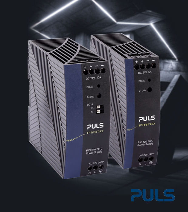
The recognized Puls quality for an attractive price
The PIANO PIC series is designed for applications that require reliable DIN rail power supplies, which are focused to deliver the most widely required customer functionalities. Our PIC units offer this simplicity without making compromises on PULS’ renowned qualities; efficiency, service lifetime, reliability and size.
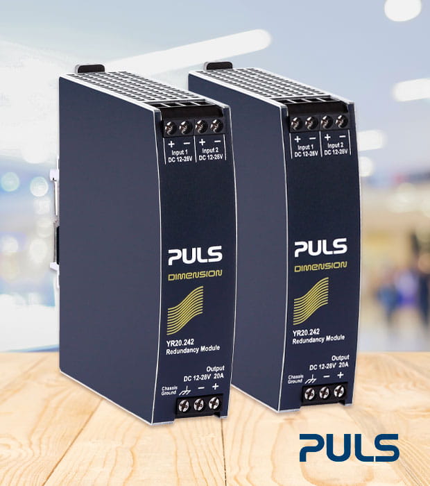
Redundant systems without redundancy modules
With the CP series, PULS offers a unique feature: Power supplies with an integrated decoupling function based on efficient MOSFET technology. This means there is no need for additional redundancy modules in 1+1 and n+1 redundant systems.

Quality solutions for motion controls
TER - Tecno Elettrica Ravasi, is our Italian supplier specializing in the manufacture of control stations. TER has over 60 years of experience in the manufacture of control stations.

LOOP Heater for optimal heat distribution
Thanks to their loop design, LOOP heating elements offer excellent heating performance and ensure optimal heat distribution. Read more now!

Compact electronic overcurrent protection PISA-M
PISA-M is a 4-channel electronic fuse for 12 and 24 V DC systems. The smallest 4-channel electronic fuse with a width of only 22.5 mm!
