PULS
24 V dc UPS integrated battery 5 Ah
A DC-UPS system comprises a control unit with integrated 5 A high power battery, and a power supply with suitable power for the application. The battery is easy to replace by undoing the screw at the front. In case of a power failure, the battery is automatically connected and feeds the connected loads. The UPS requires only one (1) 12 V battery which then transforms up the battery voltage to 22.3 V dc, one does not need to match 2 batteries with each other and the output voltage does not follow the battery's discharge curve but is constant at 22.3 V. The battery capacity is utilised 100% compared with two series-connected batteries where one of the batteries will not be fully charged.
Two relay outputs indicate status; module ready (battery capacity >85%) and module active (buffer mode). The control unit tests the battery's condition in cycles, when it is time to replace the battery, a relay output is activated (replace battery). One sensor measures the temperature and optimises the final charging voltage. The buffer time can be set in different time ranges to save battery capacity, when a constant discharge is selected, the output voltage will be active until the battery reaches deep discharge and the control unit disconnects the battery.
A fault on the battery fuse drops the Ready output and a red LED lights on the control unit. The output has a current limit and shuts itself off after about 5 seconds after a short-circuit to save the battery and at the same time avoid tripping the battery fuse. With a short-circuit in buffer mode, the module will deliver approx. 20 A which helps to trip any secondary fuse. Monitoring of the battery fuse and current limitation with short-circuits gives an increased safety and a guarantee that the UPS will function after a short circuit. The input is galvanically isolated from the output side.
Backup times
|
|

- Load current 10 A
- Only one 12 V battery
- Integrated high power battery of 5 Ah
- Relay outputs for status


Selected variant
Specifications
| Input Voltage From The Unit | 24 V DC |
|---|---|
| Input Voltage From battery | 12 V DC |
| Input voltage for battery connection | 22.8 V DC |
| Input Current During Charging Of Aggregates | 1.3 A |
| Type Power Supply | DC-UPS |
| Output current at 24 V dc | 10 A |
| Output Voltage at Battery | 22.25 |
| Output Voltage Normal Operation | 24 V DC |
| Output Voltage At Buffering | 22.25 V DC |
| Output current for battery operation max | 10 A (15 A @ 5 s) |
| Output Current During Normal Operation Via The Unit Max | 15 A |
| Ripple. max | 20 mV pp |
| Temperature Range Without Derating From | 0 °C |
| Temperature Range Without Derating To | 40 °C |
| Efficiency | 97.8 % |
|---|---|
| Life span | 137 400 h @ 10 A, 40 °C |
| MTBF (IEC 61709) | 886 000 h @ 10 A, 40 °C |
| Width | 123 mm |
| Height | 124 mm |
| Depth | 119 mm |
| Weight | 2.85 kg |
| Approvals | ABS, CB, CE, CSA, CSA US, EX, GL, IECEx, UL |
| Material Protection | Aluminium |
| IP Class | IP20 |
| Charging The Battery Type | 1.5 A |
| Permitted Battery Sizes | 5 Ah |


Product description
A DC-UPS system comprises a control unit with integrated 5 A high power battery, and a power supply with suitable power for the application. The battery is easy to replace by undoing the screw at the front. In case of a power failure, the battery is automatically connected and feeds the connected loads. The UPS requires only one (1) 12 V battery which then transforms up the battery voltage to 22.3 V dc, one does not need to match 2 batteries with each other and the output voltage does not follow the battery's discharge curve but is constant at 22.3 V. The battery capacity is utilised 100% compared with two series-connected batteries where one of the batteries will not be fully charged.
Two relay outputs indicate status; module ready (battery capacity >85%) and module active (buffer mode). The control unit tests the battery's condition in cycles, when it is time to replace the battery, a relay output is activated (replace battery). One sensor measures the temperature and optimises the final charging voltage. The buffer time can be set in different time ranges to save battery capacity, when a constant discharge is selected, the output voltage will be active until the battery reaches deep discharge and the control unit disconnects the battery.
A fault on the battery fuse drops the Ready output and a red LED lights on the control unit. The output has a current limit and shuts itself off after about 5 seconds after a short-circuit to save the battery and at the same time avoid tripping the battery fuse. With a short-circuit in buffer mode, the module will deliver approx. 20 A which helps to trip any secondary fuse. Monitoring of the battery fuse and current limitation with short-circuits gives an increased safety and a guarantee that the UPS will function after a short circuit. The input is galvanically isolated from the output side.
Backup times
|
|
Related
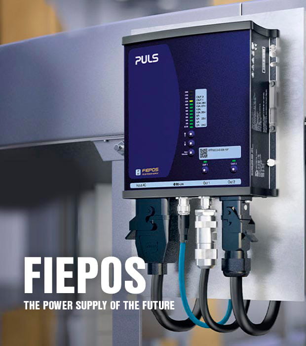
Fiepos — The power supply of the future
The need for flexible, modular systems shapes machine and system engineering. Decentralization of the system components has proven to be an important factor for success.
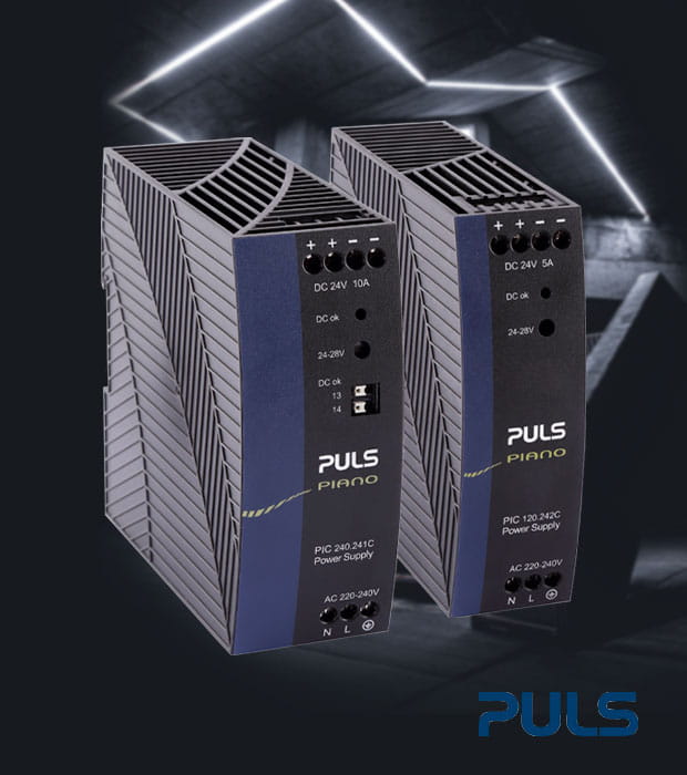
The recognized Puls quality for an attractive price
The PIANO PIC series is designed for applications that require reliable DIN rail power supplies, which are focused to deliver the most widely required customer functionalities. Our PIC units offer this simplicity without making compromises on PULS’ renowned qualities; efficiency, service lifetime, reliability and size.
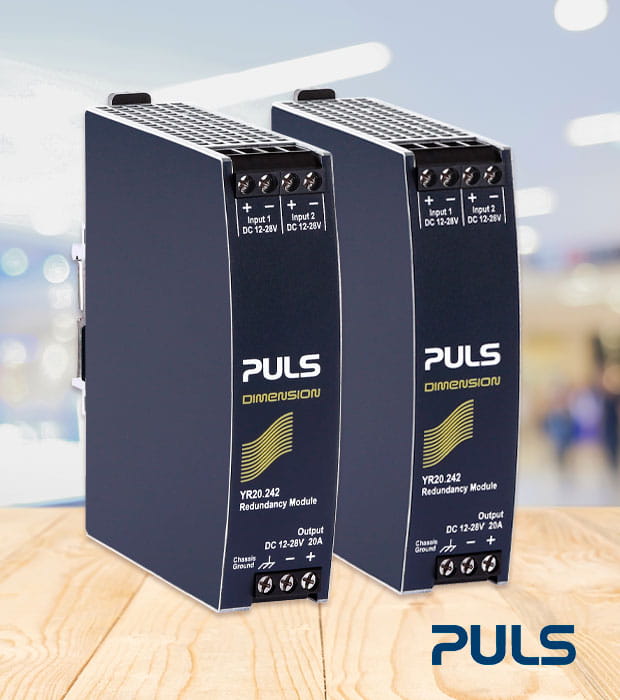
Redundant systems without redundancy modules
With the CP series, PULS offers a unique feature: Power supplies with an integrated decoupling function based on efficient MOSFET technology. This means there is no need for additional redundancy modules in 1+1 and n+1 redundant systems.

Quality solutions for motion controls
TER - Tecno Elettrica Ravasi, is our Italian supplier specializing in the manufacture of control stations. TER has over 60 years of experience in the manufacture of control stations.

LOOP Heater for optimal heat distribution
Thanks to their loop design, LOOP heating elements offer excellent heating performance and ensure optimal heat distribution. Read more now!

Compact electronic overcurrent protection PISA-M
PISA-M is a 4-channel electronic fuse for 12 and 24 V DC systems. The smallest 4-channel electronic fuse with a width of only 22.5 mm!
